Performance evaluation of ReX 100 on retrofitted RCC members
Case Study
Om Narayan Singh, Applications Engineer, Nirixense Technologies
Sai Srikar Kolluri, Product Manager, Nirixense Technologies
Divya Koppikar, Product and UI/UX Designer, Nirixense Technologies
(January 2026)
Introduction:
Rehabilitation and retrofitting of reinforced cement concrete (RCC) structures commonly involve the application of polymer-modified repair systems, micro-concrete jacketing, and Fiber Reinforced Polymer (FRP) strengthening. While these techniques restore durability and structural capacity, they significantly modify surface characteristics and effective cover depth, which can influence non-destructive testing (NDT) outcomes.
This report presents a comprehensive on-site performance evaluation of the ReX 100 rebar scanner, focusing on its ability to reliably detect embedded steel reinforcement under three distinct retrofitting conditions:
- Polymer-applied repair zones
- Micro-concreted repair zones
- FRP-strengthened RCC beam inside a water tank
The study validates the applicability of ReX 100 for post-retrofitting inspection, quality assurance, and structural health assessment. Watch the full on-site validation of ReX 100 across the entire structural retrofitting process in our YouTube video below – from corrosion mapping on distressed concrete through quality assurance verification of completed polymer micro-concrete and CFRP strengthened systems.
Objectives of the study:
The objectives of the site visit and testing were to:
- Evaluate the performance of ReX 100 under different retrofitting materials and thicknesses
- Verify reinforcement detectability after repair and strengthening
- Assess signal stability and repeatability in real field conditions
- Establish confidence for ReX 100 usage in rehabilitation and SHM applications
Site description:
The site consists of an existing RCC structure undergoing rehabilitation due to age-related deterioration and exposure to aggressive environmental conditions.
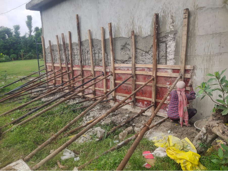
Figure 1: Shuttering and support system in place after placement of micro-concrete for section restoration of RCC wall.
Deficiencies were observed at the site such as surface degradation, corrosion-induced damage, and reduction in effective cover in beams, columns, and walls. Retrofitting measures adopted at the site included:
- Polymer-modified repair for shallow deterioration
- Micro-concrete jacketing for deeper section loss
- CFRP strengthening of beams inside a water tank
Temporary scaffolding, staging, and formwork systems are provided to facilitate safe execution of repair works.
Depth based retrofitting strategy:
The repair methodology at site is governed by the depth of deterioration and required restoration thickness, as assessed during condition evaluation.
Polymer-applied repair zones
In regions where the repair depth is less (40mm), polymer-modified repair is adopted. These zones primarily involve surface-level distress and limited cover loss. The polymer system acts as a high-adhesion bonding medium and enhances impermeability and durability, and restores surface integrity without significant increase in dimensions.

Figure 2: Polymer-modified repair region showing reinforcement bars identified and mapped using ReX 100 scanning.

Figure 3: Rebar detection graph obtained from ReX 100 scan of a polymer-coated RCC wall, showing vertical reinforcement bars.

Figure 4: Rebar detection graph obtained from ReX 100 scan of the polymer-coated RCC wall, showing horizontal reinforcement bars.
Micro-concreting repair zones
In regions where deterioration depth is more (greater than 40mm), micro-concrete jacketing is implemented to restore the original cross-section and protect reinforcement. Micro-concreting involves:
- Exposing RCC member and removing loose concrete
- Cleaning surface using water jet and wire brush
- Cleaning reinforcement and applying rust remover (rusticide)
- Providing additional reinforcement where required and applying rust passivator
- Erecting formwork of required dimensions
- Pouring micro-concrete into the shuttered zone
The formwork system consists of vertical panels and inclined steel props to ensure dimensional stability during concreting.
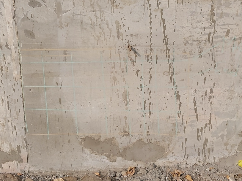
Figure 5: Micro-concreting repair region showing reinforcement bars identified and mapped using ReX 100 scanning.
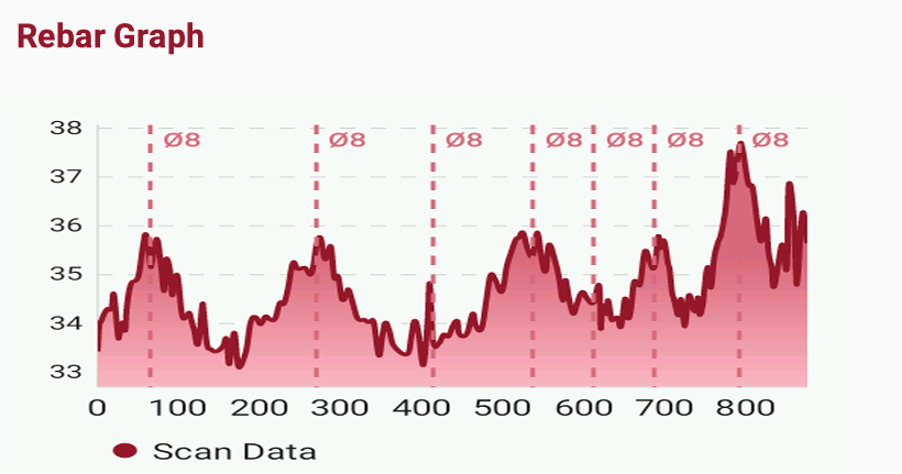
Figure 6: Rebar detection graph obtained from ReX 100 scan of a micro-concreting RCC wall, showing vertical reinforcement bars.
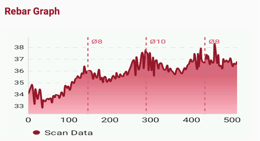
Figure 7: Rebar detection graph obtained from ReX 100 scan of the same micro-concreting RCC wall, showing horizontal reinforcement bars.
FRP strengthening of beam inside water tank
An internal RCC beam located inside a water tank was strengthened using Carbon Fiber Reinforced Polymer (CFRP). The beam is subjected to high humidity, moisture exposure, and cyclic wet–dry conditions, which accelerate deterioration of conventional reinforcement. The application process involves:
- Surface grinding and cleaning of beam
- Application of epoxy primer
- Wet lay-up placement of CFRP fabric
- Removal of entrapped air to ensure full bond
The FRP layer acts as an external tensile reinforcement, improving flexural capacity without increasing member size.
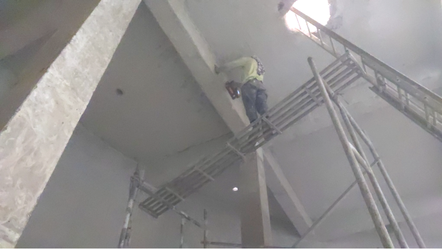
Figure 8: FRP-strengthened region studied using ReX 100 scanning.
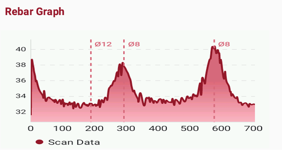
Figure 9: Rebar detection graph obtained from ReX 100 scan of a FRP jacketed beam, showing stirrups reinforcement.
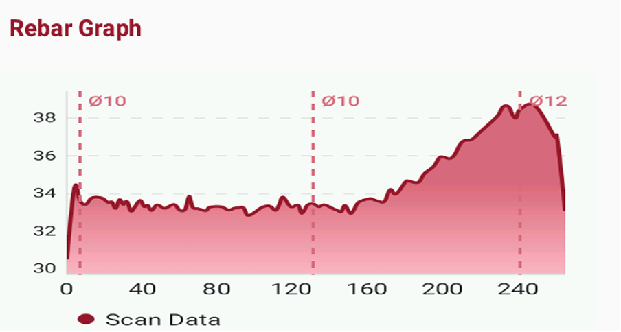
Figure 10: Rebar detection graph obtained from ReX 100 scan of a FRP jacketed beam, showing main longitudinal reinforcement.
Observations of ReX 100 rebar scanning
- Reinforcement is clearly detected beneath polymer-applied zones, micro-concrete jacketing and CFRP-strengthened beam
- Signal response is stable and repeatable across all conditions
Polymer layers, micro-concrete overlays, and CFRP laminates are non-metallic and do not shield electromagnetic signals. ReX 100 maintains reliable detection capability despite increased cover depth and modified surface materials, and is therefore suitable for quality assurance (QA) of such projects.
Recommendations
- ReX 100 is recommended for post-repair verification in rehabilitation projects
- The device is suitable for quality assurance of polymer, micro-concrete, and FRP systems
- ReX 100 can be effectively integrated into periodic structural audit programs for retrofitted RCC structures.