Evaluation of reinforcement mapping during retrofitting using ReX 100 Rebar Scanner
Case Study
Om Narayan Singh, Applications Engineer, Nirixense Technologies
Sai Srikar Kolluri, Product Manager, Nirixense Technologies
Divya Koppikar, Product and UI/UX Designer, Nirixense Technologies
(January 2026)
Introduction and background:
Retrofitting of reinforced concrete (RC) structures requires a clear and reliable understanding of the existing reinforcement layout, cover depth, bar spacing, and corrosion condition before any strengthening intervention is executed. In ageing industrial structures, corrosion-induced deterioration of beams, columns, and slabs often leads to loss of cross-section, reduced bond strength, and compromised structural capacity.
At a commercial facility in Mumbai, structural strengthening was ongoing due to observed distress in multiple RC components. As part of the retrofitting scheme, the depth of beams was increased to enhance flexural and shear capacity. During demolition and surface preparation, active corrosion was observed in beams, columns, making reinforcement assessment critical before finalizing jacketing and section enlargement details.
This case study documents the application and field verification of the ReX 100 rebar scanner under real retrofitting conditions where reinforcement was partially and fully exposed, allowing direct validation of scanner performance. Watch the full on-site validation of ReX 100 across the entire structural retrofitting process in our YouTube video below – from corrosion mapping on distressed concrete through quality assurance verification of completed polymer micro-concrete and CFRP strengthened systems.
Objective of the study:
The objective of the present study is to evaluate the accuracy and reliability of the ReX 100 rebar scanner under actual retrofitting conditions. The study aims to establish a direct correlation between scanner-detected reinforcement details and physically exposed reinforcement to validate field performance. Particular emphasis is placed on assessing scanner effectiveness in beams and columns affected by corrosion. Additionally, the study seeks to demonstrate a controlled, repeatable, and practical scanning methodology that can be reliably adopted in retrofitting and strengthening projects.
Structural condition and retrofitting context:
Observed structural distress
Visual inspection of the structure prior to scanning revealed multiple indicators of deterioration. Corrosion staining and concrete delamination were observed on beams, while several columns exhibited reduced cover with partially exposed reinforcement. These distress patterns are characteristic of long-term durability issues arising from moisture ingress and exposure to an aggressive industrial environment, leading to corrosion of reinforcement and progressive deterioration of the surrounding concrete.
Retrofitting activity
The retrofitting strategy implemented at the site involved increasing the depth of existing beams to restore and enhance their flexural and shear capacity. This process required partial exposure of existing reinforcement to ensure adequate anchorage and bonding between the old and newly added concrete. Surface preparation and jacketing operations were carried out as part of the strengthening works. Such interventions necessitate accurate reinforcement mapping to prevent inadvertent cutting of primary reinforcement and to ensure proper detailing of additional structural elements.
Test locations and components investigated
ReX 100 scanning was carried out at three critical locations: location L1 (beam), L2 (beam) and L3 (column). All three locations had reinforcement exposed, provided an ideal scenario for direct comparison between detected and actual reinforcement.
Test methodology:
Surface preparation and reference setup
To ensure consistent and repeatable scanning, the following steps were taken:
- A ply sheet was placed over the exposed reinforcement surface. The ply acted as a uniform scanning interface, simulating real concrete surface conditions
- Start and end points of the scanning zone were clearly marked
- Straight reference lines were drawn to control scanner movement
This procedure minimized errors due to surface irregularities and ensured alignment consistency across scans.
Scanning procedure
The scanning protocol followed is detailed below:
- ReX 100 scanner was moved along the predefined straight path.
- Uniform speed and continuous contact were maintained.
- Multiple passes were performed to confirm repeatability.
- Data were recorded for bar location, spacing, and depth.
The same methodology was consistently applied at all three test locations.
Observations:
The ReX 100 scanner clearly and consistently detected longitudinal reinforcement in both beams and columns. The identified bar locations and alignment showed close agreement with the physically exposed reinforcement. Even in areas affected by corrosion, the scanner demonstrated high positional accuracy, confirming its suitability for use under real site conditions.
The reinforcement spacing was observed to vary along the length of the structural members and was not uniform. This variation was clearly verified through direct physical exposure of the reinforcement. The observed spacing pattern indicates that reinforcement placement follows the original structural design intent and site-specific detailing requirements, rather than a constant spacing throughout the member, which is typical of many RCC constructions.
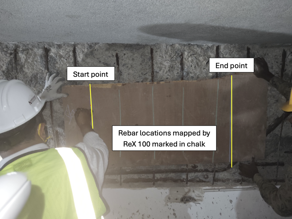
Figure 1: Beam location L1.
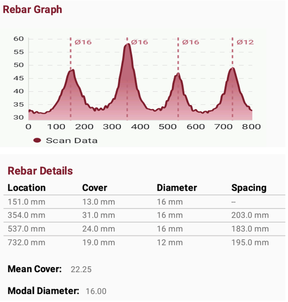
Figure 2: Results on beam location L1.
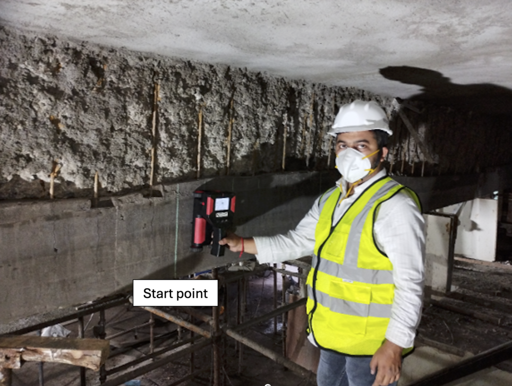
Figure 3: Beam location L2.
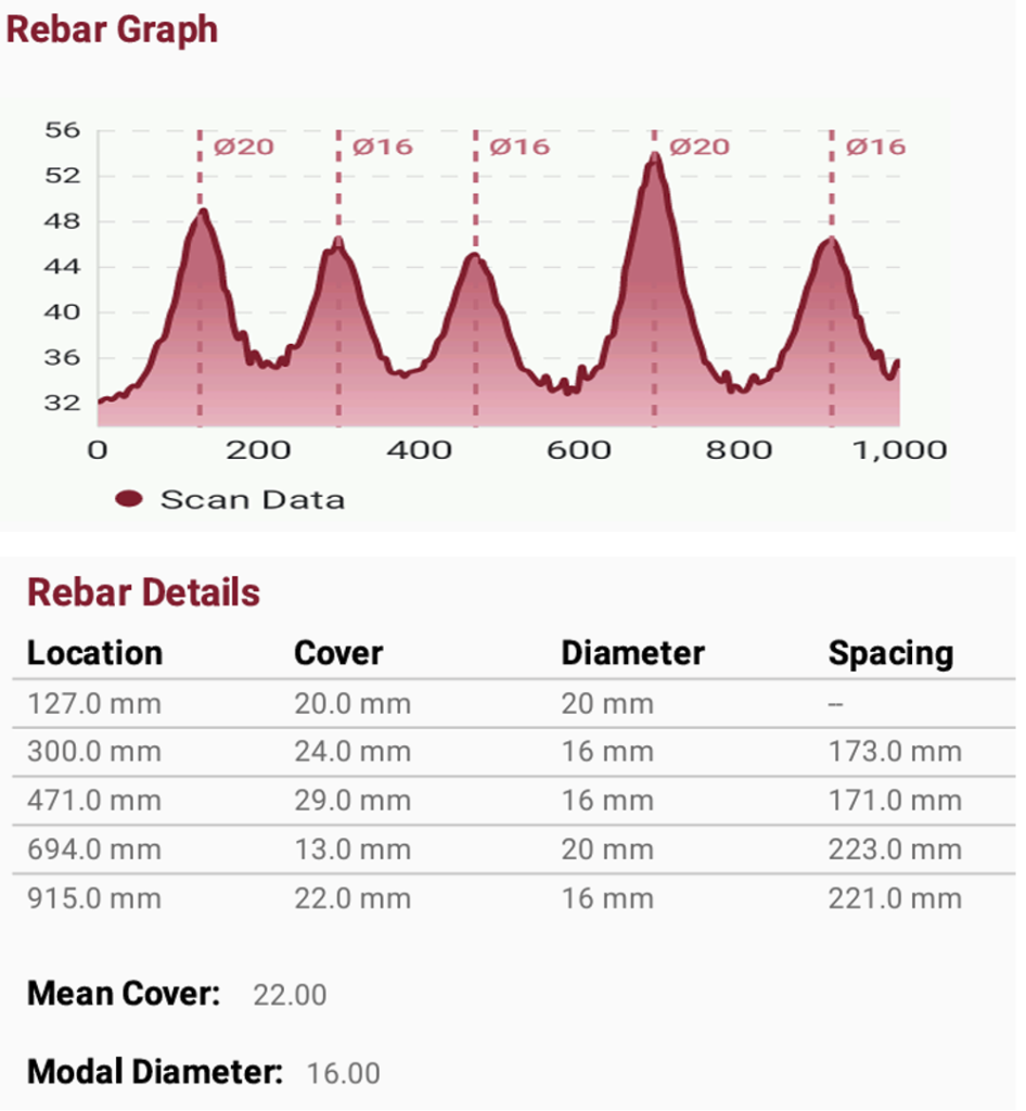
Figure 4. Results on beam location L2.
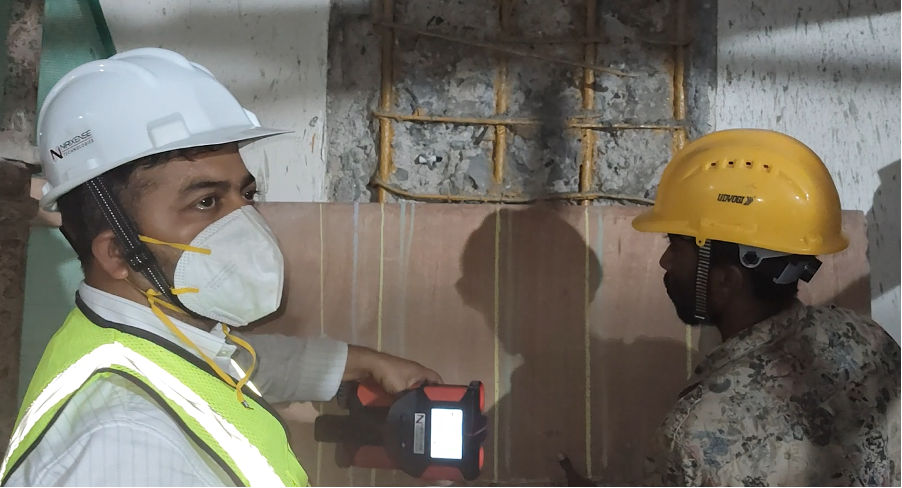
Figure 5. Column location L3.
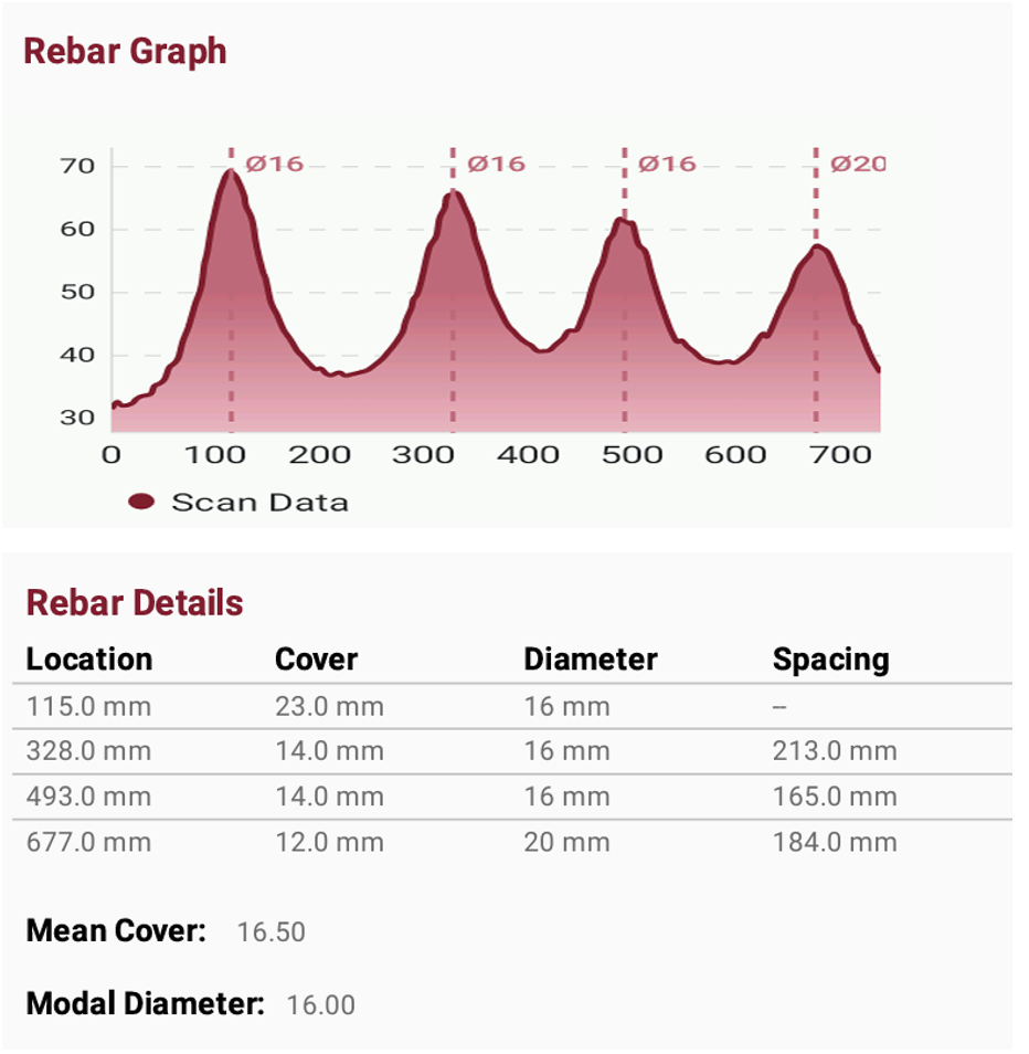
Figure 6. Results on column location L3.
Influence of corrosion on detection
- Corroded reinforcement produced distinct signal variations
- Zones with visible section loss showed localized irregularities in signal response
- The scanner successfully identified reinforcement presence even where corrosion products were visible
This confirms that ReX 100 remains effective under real deterioration conditions, not just laboratory-controlled environments.
Verification with exposed reinforcement
As the reinforcement was already exposed at the selected locations, direct visual verification of scanner results was possible. The bar positions indicated by the ReX 100 scanner coincided closely with the actual reinforcement layout observed on site. No significant deviation was noted between detected and exposed reinforcement, providing strong field-level validation of the scanner’s accuracy and reliability.
Engineering interpretation
From an engineering assessment perspective, the ReX 100 scanner effectively supports decision-making during retrofitting operations. Accurate identification of reinforcement location and spacing helps prevent accidental cutting of load-carrying bars and reduces the risk associated with drilling or anchorage installation. The non-destructive nature of the technique allows verification of reinforcement details prior to invasive works, thereby minimizing construction risks, delays, and potential rework. Its reliable performance in corrosion-affected zones further enhances its applicability for ageing industrial and commercial structures.
Practical Significance for Retrofitting Projects
This study demonstrates that ReX 100 is highly suitable for:
- Studying rebars in beam depth enhancement, column jacketing and strengthening projects
- Structural audits prior to demolition or modification
- Verification of as-built reinforcement in old RCC structures
Its use leads to:
- Improved construction safety
- Better retrofit detailing accuracy
- Reduced uncertainty in structural intervention
Conclusions
Based on field observations and direct verification:
- ReX 100 accurately detects reinforcement location, spacing, and continuity
- Scanner performance remains reliable under corrosion-affected conditions
- The tool proves to be an effective non-destructive evaluation instrument for retrofitting applications
The case study confirms that ReX 100 is a practically validated solution, not merely a laboratory-tested device.
Recommendations for using ReX 100 in such an application
- Always establish clear reference lines before scanning
- Perform multiple scans for critical retrofit zones
- Use scanning data in conjunction with engineering judgment and visual inspection
- In highly deteriorated zones, validate scanner findings through controlled exposure where feasible